The pump room integrated in the pool is located in a ladder for example for the Desjoyaux swimming pool brand. Usually no additional equipment can be added to it and no pool pump room diagram is made.
Nfpa 20 Compliant Fire Pump House
3D Model acad airport autocad Autocad Blocks Beam Bridge cad cad blocks cad details Concrete Crane Cross Section drawing dwg dwg free Factory Fire system Foundation free dwg hospital Hotel hydraulic Lighting Mechanical pipe Plant Plumbing Work.

. Download Free MEP Calculation Excel Sheets AutoCAD Drawings and Training Courses for HVAC Firefighting Plumbing and Electrical Systems Design. Floor Layout Planning Pump room. Sufficient clear space provided above pump for motor removal.
All details and components of fire pump room according to NFPA 20. Sizing it as accurately as possible. A pump room have fire pump which is a part of a fire sprinkler systems water supply and powered by electric diesel or steamThe pump intake is either connected to the public underground water supply piping or a static water source eg tank reservoir lake.
The space will be enough for installing 3 pump units 5m3sec each and auxiliary machines and for O M. On the suction I will use a pipe diameter of. I will design my system so that from the pump there is a 34 copper tube main distributor there will be a 34 take-off from this distributor on the ground floor to the second floor level where the bath is located.
Oct 23 2018 - Download Fire Pump Room Design Details and Requirements PDF Notes. Free CAD and BIM blocks library - content for AutoCAD AutoCAD LT Revit Inventor Fusion 360 and other 2D and 3D CAD applications by Autodesk. Pump Discharge nozzle minimum 1 m from rack.
The design drawings shown in Figure 2-22 for construction of Central and West Pump Stations and. The fire rating can be reduced to a one-hour rating when the fire pump enclosure is located in a fully sprinkled non high-rise building. All details and components of fire pump room according to NFPA 20.
That one dealt with NFPA 20 and NFPA 70 NEC concerning the in sight of requirement for. You can exchange useful blocks and symbols with other CAD and BIM users. Check that your exhaust system design is sized correctly with a Clarke engine.
More from my site. Pump motor is toward Rack. Pump not located under pipeway in process unit.
Pump Room Ventilation Find out how much air flow you need in a pump room with a Clarke engine. Before drawing the swimming pool pump room diagram it is important to confirm the dimensions of the room itself. Pump Room Ventilation Find out how much air flow you need in a pump room with a Clarke engine.
The pump provides water flow at a higher pressure to the sprinkler system risers and hose standpipes. Use HVAC Plans solution to create professional clear and vivid HVAC-systems design plans which represent effectively your HVAC marketing plan ideas develop plans for modern ventilation units central air heaters to display the refrigeration systems for automated buildings control environmental control and energy systems. Fire Pump Room Layout Drawing cincinnati enquirer cincinnati com all careers at my next move firefighting wikipedia short term projections central various considerations in equipment layout in the scpokemon scp foundation coj net fire and rescue plan review procedures crotched mountain bennington nh groupon.
Pump is located close to equipment from which it taking its suction. Check that your exhaust system design is sized correctly with a Clarke engine. Plumbing and Piping Plans solution extends ConceptDraw PRO v1022 software with samples templates and libraries of pipes plumbing and valves design elements for developing of water and plumbing systems and for drawing Plumbing plan Piping plan PVC Pipe plan PVC Pipe furniture plan Plumbing layout plan Plumbing floor plan Half pipe plans Pipe bender plans.
Centreline of Discharge Nozzles on common centreline for rows of pumps as far as possible. Free CADBIM Blocks Models Symbols and Details. NFPA 20 requires the fire pump room to have a minim um two-h ou r fire rating when located in a high-rise building.
Hvac Pump Room Layout. ArtStation - DESIGN AND SHOP DRAWING OF PUMP ROOM WITH COMPLETE DETAILS. CAD blocks and files can be downloaded in the formats DWG RFA IPT F3D.
From the pool to the pump room On the general plan of the pool we draw the different pipes layout connecting the fittings of the pool with the equipment in the pump room. The above photo is one I drew on MS Paint for another discussion about pump room design code violations. Chilled Water Pump Room Details Layout Plan CAD Template DWG.
Pump Room Tank Layout Figure 2 below is the same as in the companion paper on water supplies and is included here to further reinforce the design requirements. Figure 2 Fire Pump Room Tanks The tanks shown in Figure 1 are circular steel tanks complying with AS2304 2011 Water Storage Tanks for Fire protection Systems. For an easy understanding we use different colours and the location.
50 Design Detail and Structural Stability 15 51 Shape 52 Shallow End 53 Bottom Slope 54 Area Marked 55 Pool Walls 551 Ledges 552 Pools Without Gutters 56 Diving Areas 561 Head Room 562 Diving Boards and Platforms 563 Steps and Guard Rails for Diving Boards Table 1 57 Ladders Recessed Steps and Stairs 571 Location.

Pump Room Drawing In Manali Chennai Id 10269048588
A Pump Room Layout Showing 4 Locations Type 2 Download Scientific Diagram

Pump Room Layout Plan And Plumbing Structure Drawing Details Dwg File Cadbull
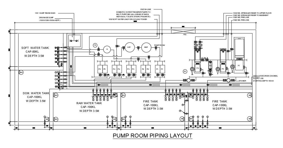
A Layout Of 30x12m Underground Pump Room Detail Drawing Is Given In This Autocad Drawing File Download Now Cadbull

Illustration Of The Pump Room For Group Ii Download Scientific Diagram

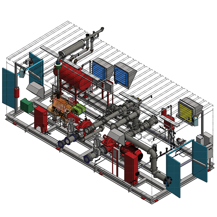
Artstation Design And Shop Drawing Of Pump Room With Complete Details

Artstation Design And Shop Drawing Of Pump Room With Complete Details

Fire Pump Room 3d Cad Model Library Grabcad
0 comments
Post a Comment